Design for Manufacturability (DFM): The Complete Overview

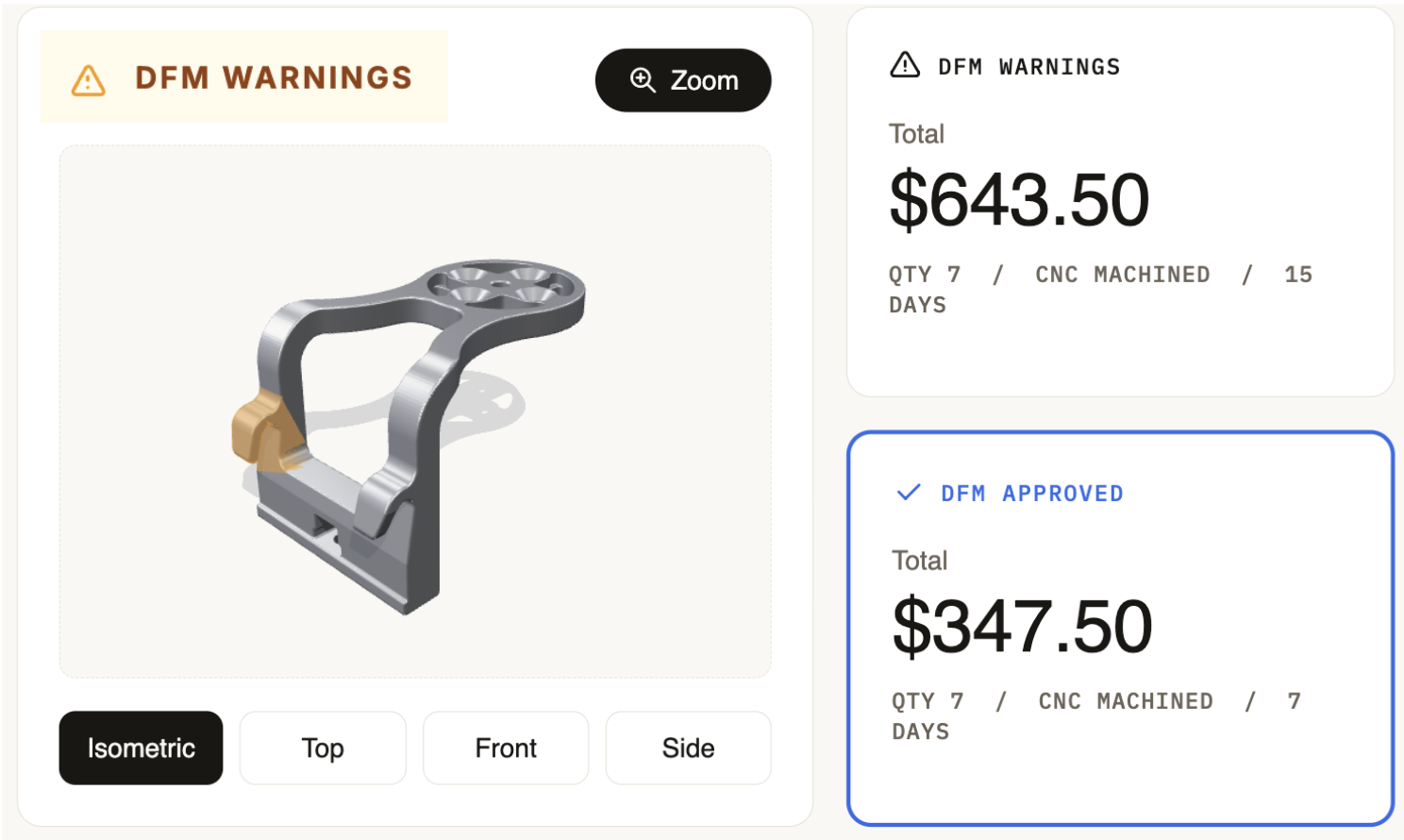
When you design a part, you expect it to come out looking exactly like your CAD model. Sometimes that happens. But the move from design to an actual part is not always that simple.
Where you are in the product lifecycle also changes what design for manufacturing (DFM) means. If you are at the prototype stage, 3D printing or CNC machining is probably your best process, rather than die casting or injection molding. But the rules of DFM are different for each of those processes. And the steps and processes for prototypes are different from mass production too. So DFM looks different depending on where you are.
This overview covers the basics of DFM, breaks down what changes between the prototype and production stages, walks through the rules you need to know for each, and looks at whether you can ever get away with ignoring DFM.
What is DFM
DFM means designing a part so the process you picked can actually make it, reliably and without unnecessary added costs. It sounds simple, but DFM is not one fixed rulebook. The rules change depending on the manufacturing process (CNC machining, sheet metal, injection molding, 3D printing), and they change depending on what stage you are in.
A rule that matters a lot for injection molding, like uniform wall thickness, does not apply to CNC machining. A tolerance that is totally fine for one prototype part can become expensive once you have higher volumes in mass production. Good DFM means knowing which rules apply to your process and your stage, not memorizing one universal checklist.
DFM Focus: Prototypes vs Mass Production
DFM at the prototype stage and DFM at the mass production stage are answering two different questions. Prototype DFM asks if this part can be made at all, fast enough that you can test it and validate something. Production DFM asks if this part can be made at the lowest cost per unit, at volume, with consistent quality, every single time. The constraints that matter shift depending on which question you are trying to answer. Some rules apply at any volume because of the law of physics. Other rules only start to matter once you are paying for tooling, automation, or thousands of cycles.
DFM for Prototypes
At the prototype stage, your goal is speed and learning, not cost per unit. The DFM constraints that matter most are the ones that decide whether a part can be made at all, in the time you need. That means things like minimum wall thickness, tool access for internal features, and realistic tolerances. A feature that needs custom tooling or a five-axis setup might be technically possible, but it will blow your timeline and your budget for a part you are only making one or ten of. At this stage, the right move is usually to simplify any feature that is not critical to the test you are running. You are not optimizing for manufacturing efficiency yet. You are optimizing to get a real part in your hands so you can find out if the design works.
DFM for Mass Production
Once you move toward production volumes, the mindset changes. A tolerance that costs nothing extra on a single prototype part can add real machining time, and real cost, multiplied across 10,000 units. Tooling decisions that did not matter for a prototype, like multi-cavity injection molds, automated part ejection, or draft angles optimized for fast demolding, now directly affect your unit cost. Design choices that were fine for “does this work” now get judged against “can this be made consistently, at the lowest cost, without manual rework.” This is where DFM shifts from a speed question to a cost and repeatability question, and where small geometry changes can save real money at scale.
Top DFM Rules You Must Know
DFM rules depend heavily on the manufacturing process you are using. Here is a quick reference checklist broken down by the processes you will most likely run a prototype through.
CNC Machining
CNC machining cuts material away with a rotating tool, so most of the rules come down to what the tool can physically reach and survive cutting.
- Keep wall thickness above roughly 0.8mm for metals and 1.5mm for plastics to avoid chatter or breakage during cutting.
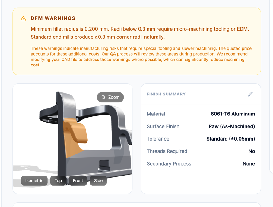
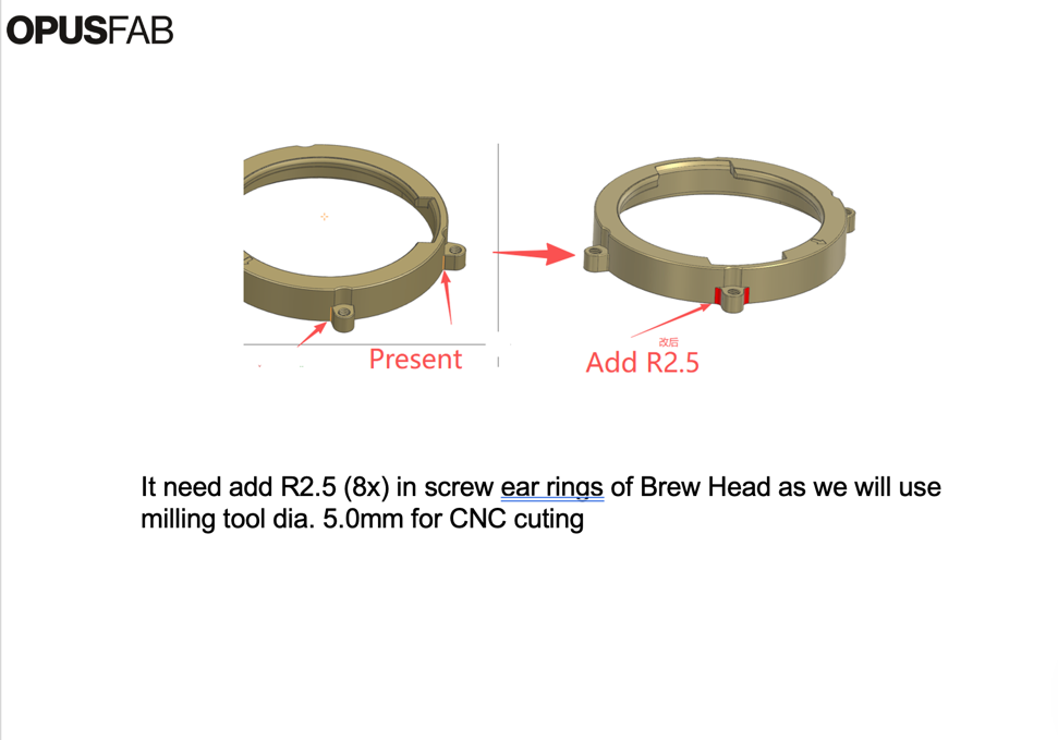
- Match internal corner radii to standard tool radii (avoid sharp internal corners, which require costly EDM work).
- Keep hole depth under about 4 times the hole diameter so standard drills can reach the bottom cleanly.
- Avoid deep, narrow pockets that require long, thin tools prone to deflection and breakage.
Sheet Metal
Sheet metal parts are cut and bent from a flat sheet, so most DFM rules here protect the material from cracking or warping at the bend.
- Keep bend radii at or above material thickness to avoid cracking at the bend.
- Keep holes and cutouts away from bend lines, generally at least 2 to 3 times material thickness from the bend.
- Avoid features that require separate operations on both sides of the sheet, which adds setup time and cost.
- Maintain consistent material thickness across the part; mixing thicknesses generally means separate parts joined together.
Injection Molding
Injection molding pushes molten plastic into a mold, so the rules focus on how the material flows and how the part releases once it cools.
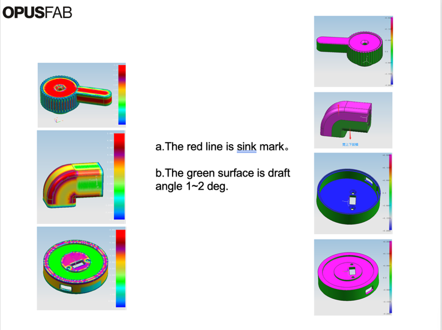
- Keep wall thickness uniform throughout the part to avoid warping, sink marks, and uneven cooling.
- Add draft angles (typically 1 to 2 degrees minimum) to every vertical wall so the part releases cleanly from the mold.
- Avoid sharp internal corners; use generous fillets to reduce stress concentration and improve material flow.
- Minimize undercuts, since each one usually requires added mold complexity like side-action tooling.
3D Printing
3D printing builds a part layer by layer, so the rules focus on what each layer can support before it needs help from extra material.
- Design overhangs under 45 degrees where possible to minimize the need for support material.
- Keep minimum feature size above your printer’s resolution limit, typically 0.4 to 1mm depending on the process.
- Orient parts to put critical load-bearing features along the strongest print axis, not across layer lines.
- Account for material shrinkage and warping on larger flat surfaces, especially with FDM.
Should You Ever Ignore DFM?
Sometimes, yes, but only for a specific reason. If you are at the very earliest concept stage and just testing form, fit, or basic function, with no intention of tooling up or scaling the design anytime soon, it can make sense to deliberately break a DFM rule to get a part faster or cheaper. You are not committing to that geometry long term. You are just trying to learn something quickly.
The risk is when you say you will change and apply DFM rules later in the development cycle. A part that ignores DFM might work fine as a single proof of concept, but if that same geometry survives into design-intent prototypes or early production parts, you will pay for it later in rework, redesign cycles, or a quote that comes back far higher than expected. The earlier you build in manufacturability, even loosely, the less expensive your surprises become down the line. DFM is not a gate you pass through once. It is a filter you tighten as your design gets closer to the part you will actually ship.
Conclusion: DFM Overview
DFM is not a single checklist you memorize once and forget. It depends on your process and where you are in the product lifecycle. Get it right early, even loosely, and you save yourself rework, delays, and surprise costs later on.
This is exactly the kind of problem OpusFab was built to solve. Instead of waiting days for a DFM review or a quote, OpusFab gives you instant DFM analysis and instant quotes, so you find out if your design works for the process you picked before you have lost a week waiting on an answer. Whether you are sending out your first prototype or scaling in production, you get the design feedback and pricing you need right away, not after a back and forth that costs you the time you were trying to save in the first place.