What Are Realistic CNC Tolerances for Most Suppliers?

Defining tolerances is one of the harder parts of putting a drawing together. Asked what a part needs, a lot of engineers answer tight, or as tight as possible, with no number attached. Tolerance is not a quality setting that gets turned up when the part matters. It is a process decision, and every step tighter changes how many setups the part takes, how fast it can be cut, how it gets inspected, and how many parts scrap before one ships.
Most CNC suppliers settle this by holding ISO 2768 medium as their house standard. That is roughly ±0.1mm on small features and ±0.3mm on features up to 120mm. Anything tighter has to be called out on the drawing, and it changes both the price and the lead time.
Default tolerances and toleranced dimensions
Every dimension on a drawing has a tolerance. Most of them are not written next to the dimension.
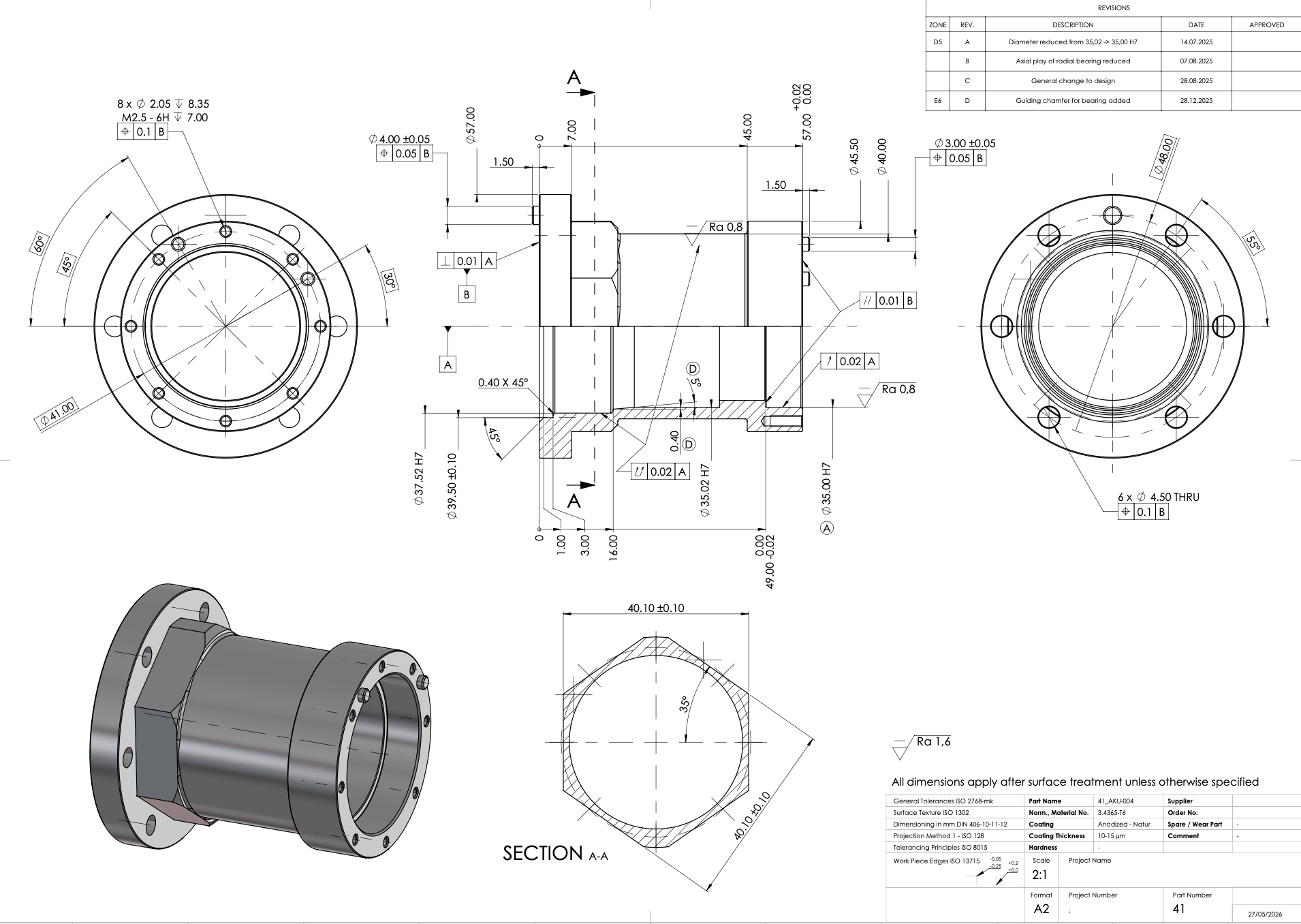
A toleranced dimension carries its limits directly, for example 25.00 ±0.02. An untoleranced dimension falls back to the general tolerance called out in the title block. On most drawings that covers 90 percent of the dimensions on the part.
When no general tolerance is specified anywhere on the drawing, the supplier picks one. Usually that is their house standard, and usually it is ISO 2768-m. This is where most tolerance disputes start. The parts arrive within the shop’s default, the design assumed something tighter, and nothing on the drawing settles the question.
What ISO 2768 covers
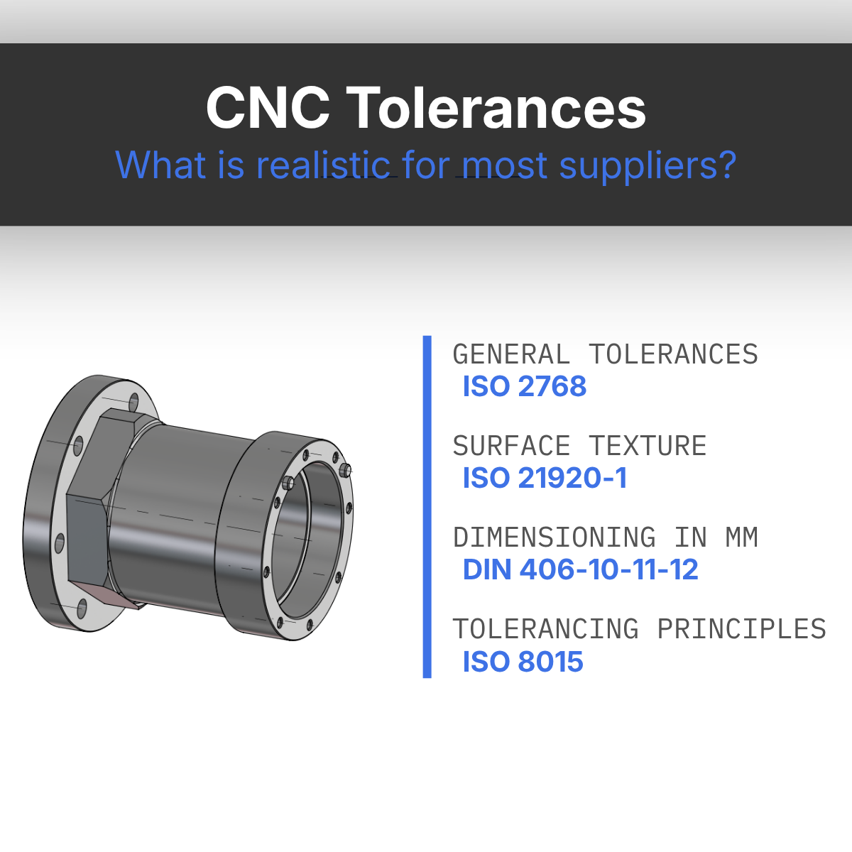
ISO 2768 is a general tolerance standard. It exists so that a drawing does not need a tolerance written against every dimension.
It comes in two parts:
- ISO 2768-1 covers linear and angular dimensions. Four classes: f (fine), m (medium), c (coarse), v (very coarse).
- ISO 2768-2 covers geometrical tolerances such as flatness, perpendicularity, symmetry, and runout. Three classes: H, K, L.
The callout combines both parts. ISO 2768-mK means medium for linear and angular dimensions, class K for geometry. ISO 2768-fH is a tighter combination. If only one letter appears, only one part of the standard has been specified.
One note on the standard itself. ISO 2768 was withdrawn in 2021 and replaced by ISO 22081, which handles general tolerances through a general geometrical specification rather than fixed class tables. In practice ISO 2768 is still what most shops quote against and what appears on most drawings in circulation, so it remains the useful reference.
Linear dimension tolerances
Permissible deviations in millimeters, from ISO 2768-1.
| Nominal size range | f (fine) | m (medium) | c (coarse) | v (very coarse) |
|---|---|---|---|---|
| 0.5 to 3 | ±0.05 | ±0.1 | ±0.2 | not specified |
| over 3 to 6 | ±0.05 | ±0.1 | ±0.3 | ±0.5 |
| over 6 to 30 | ±0.1 | ±0.2 | ±0.5 | ±1.0 |
| over 30 to 120 | ±0.15 | ±0.3 | ±0.8 | ±1.5 |
| over 120 to 400 | ±0.2 | ±0.5 | ±1.2 | ±2.5 |
| over 400 to 1000 | ±0.3 | ±0.8 | ±2.0 | ±4.0 |
| over 1000 to 2000 | ±0.5 | ±1.2 | ±3.0 | ±6.0 |
| over 2000 to 4000 | not specified | ±2.0 | ±4.0 | ±8.0 |
The tolerance grows with the size of the feature. A 20mm dimension at medium class gets ±0.2mm. The same class on a 200mm dimension gets ±0.5mm. This is the part that surprises people most often on larger parts.
Broken edges and angular tolerances
External radii and chamfer heights, in millimeters:
| Nominal size range | f | m | c | v |
|---|---|---|---|---|
| 0.5 to 3 | ±0.2 | ±0.2 | ±0.4 | ±0.4 |
| over 3 to 6 | ±0.5 | ±0.5 | ±1.0 | ±1.0 |
| over 6 | ±1.0 | ±1.0 | ±2.0 | ±2.0 |
Angular tolerances, based on the length of the shorter side of the angle:
| Length of shorter side | f | m | c | v |
|---|---|---|---|---|
| up to 10 | ±1° | ±1° | ±1°30’ | ±3° |
| over 10 to 50 | ±0°30’ | ±0°30’ | ±1° | ±2° |
| over 50 to 120 | ±0°20’ | ±0°20’ | ±0°30’ | ±1° |
| over 120 to 400 | ±0°10’ | ±0°10’ | ±0°15’ | ±0°30’ |
| over 400 | ±0°5’ | ±0°5’ | ±0°10’ | ±0°20’ |
Angular tolerance is driven by the shorter leg, not the longer one. A short feature with an angle on it gets a loose angular tolerance, which matters on small brackets and mounting faces.
Geometrical tolerances
From ISO 2768-2. All values in millimeters.
Straightness and flatness, by nominal length:
| Nominal length | H | K | L |
|---|---|---|---|
| up to 10 | 0.02 | 0.05 | 0.1 |
| over 10 to 30 | 0.05 | 0.1 | 0.2 |
| over 30 to 100 | 0.1 | 0.2 | 0.4 |
| over 100 to 300 | 0.2 | 0.4 | 0.8 |
| over 300 to 1000 | 0.3 | 0.6 | 1.2 |
| over 1000 to 3000 | 0.4 | 0.8 | 1.6 |
Perpendicularity, by length of the shorter side:
| Length of shorter side | H | K | L |
|---|---|---|---|
| up to 100 | 0.2 | 0.4 | 0.6 |
| over 100 to 300 | 0.3 | 0.6 | 1.0 |
| over 300 to 1000 | 0.4 | 0.8 | 1.5 |
| over 1000 to 3000 | 0.5 | 1.0 | 2.0 |
Symmetry, by nominal length:
| Nominal length | H | K | L |
|---|---|---|---|
| up to 100 | 0.5 | 0.6 | 0.6 |
| over 100 to 300 | 0.5 | 0.6 | 1.0 |
| over 300 to 1000 | 0.5 | 0.8 | 1.5 |
| over 1000 to 3000 | 0.5 | 1.0 | 2.0 |
Circular runout is fixed per class and does not scale with size: 0.1 for H, 0.2 for K, 0.5 for L.
Flatness at class K on a 150mm face is 0.4mm. That is a large number for anything that has to seal or mate flat against another surface. Sealing faces and bearing seats need their own callouts.
What suppliers actually hold day to day
ISO 2768-m is the standing default at most shops. It is what a quote assumes unless the drawing says otherwise.
Fine class is achievable on most features on a modern machining center, but it is not free. It usually means an extra finishing pass, tighter tool wear monitoring, and more frequent in-process checks.
Feature type matters more than the class does:
- Reamed and bored holes hold much tighter than milled features, commonly ±0.01mm to ±0.025mm.
- Turned outside diameters hold tighter than milled walls.
- Milled pockets and profiles are limited by tool deflection, especially when they are deep.
- Features spanning two setups carry the stacked error of both.
Below roughly ±0.025mm the process changes rather than just tightens. That range brings in grinding, jig boring, temperature-controlled inspection, or all three. Most general CNC suppliers will either quote it at a significant premium or decline it.
What limits tolerance in practice
Machine condition and spindle runout set the floor. Beyond that:
Number of setups. Every setup introduces its own error. Two features that must be tightly located to each other should be machined in the same setup wherever the geometry allows it.
Workholding and part rigidity. Thin walls, tall bosses, and long unsupported spans deflect under cutting force and clamping pressure. The part can measure in tolerance in the fixture and out of tolerance once released.
Material behavior. Aluminum machines predictably. Stainless work hardens and holds heat. Plastics move with temperature and humidity, and acetal and nylon in particular will not hold metal tolerances regardless of the machine.
Thermal expansion. Aluminum moves about 0.023mm per 100mm for every 10°C change. On a 300mm part that is meaningful at fine class, which is why tight parts are inspected in a controlled room rather than at the machine.
Depth to diameter ratio. A hole four diameters deep will not hold the same position and roundness as a shallow one. The same applies to deep pockets and long slots.
What tight tolerances cost
Tightening a tolerance changes the process, not just the inspection.
- Slower feeds and additional finishing passes add cycle time on every part.
- More setups mean more labor and more fixturing.
- Inspection moves from a caliper check to CMM time, and CMM reports are charged separately at most shops.
- Scrap rates rise. A part that scraps at final inspection carries the full cost of everything done before it.
The practical consequence is that tolerancing an entire drawing at fine class raises the price of every feature on the part, including the ones where it makes no functional difference. On a 40 feature part with four that actually matter, that is a large amount of money spent on nothing.
How to tolerance a part
Set a general tolerance in the title block. ISO 2768-mK is a reasonable default for most machined parts and matches what most suppliers assume anyway.
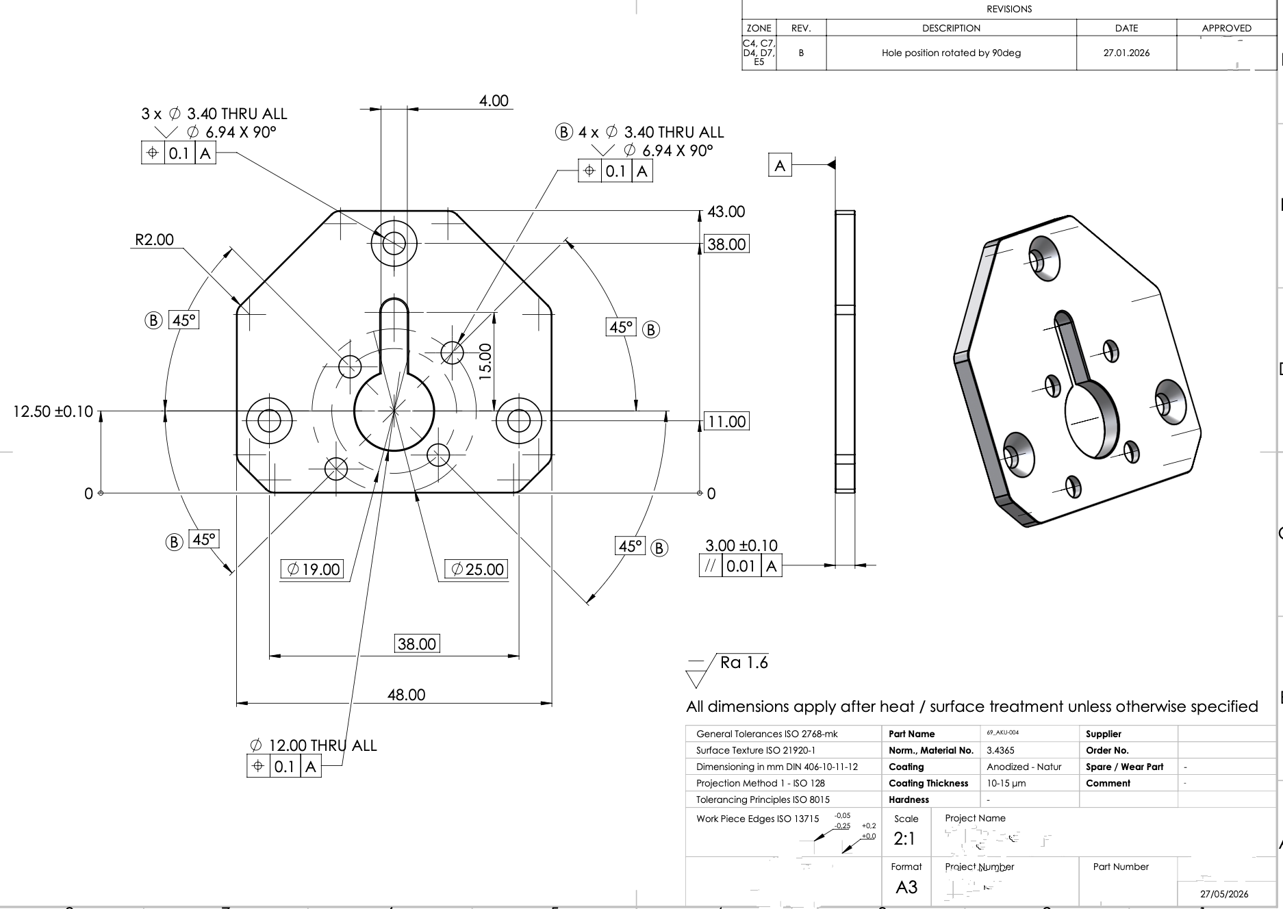
Tighten only the features that carry a function: a press fit, a bearing seat, a sealing face, a mating hole pattern, a sliding surface. Everything else can sit at the general tolerance.
Tolerance the function rather than the dimension chain. If two holes need to line up with a mating part, position them from a datum that reflects how the part is actually assembled, not from whichever edge was convenient when the model was built.
Confirm the supplier’s default before the order rather than after. A one line question about which general tolerance a quote assumes prevents most of the arguments that happen after parts arrive.
The short version
Realistic expectations for most CNC suppliers, without special callouts:
- ±0.1mm on small features, ±0.3mm on features up to 120mm, growing with size
- Reamed and bored holes at ±0.01mm to ±0.025mm
- Flatness in the range of 0.1mm to 0.4mm depending on face size
- Anything under ±0.025mm treated as a special process with a matching price
Tolerances are one of the most common reasons a quote comes back different from what was expected, and one of the most common reasons parts get rejected on arrival. OpusFab returns DFM feedback along with the quote, so tolerance problems are flagged before the order goes in rather than after the parts are cut.